45 Victoria Road, Bantry Bay - Lateral Support
Client: Private
Main Contractor: AVH Construction
Bulk Excavation Contractor: GL Conradie Plant Hire
Architect: KMH Architects
Engineer: Sippel & De Lange
Geotechnical Designers: Peragage Geotechnical Consultants
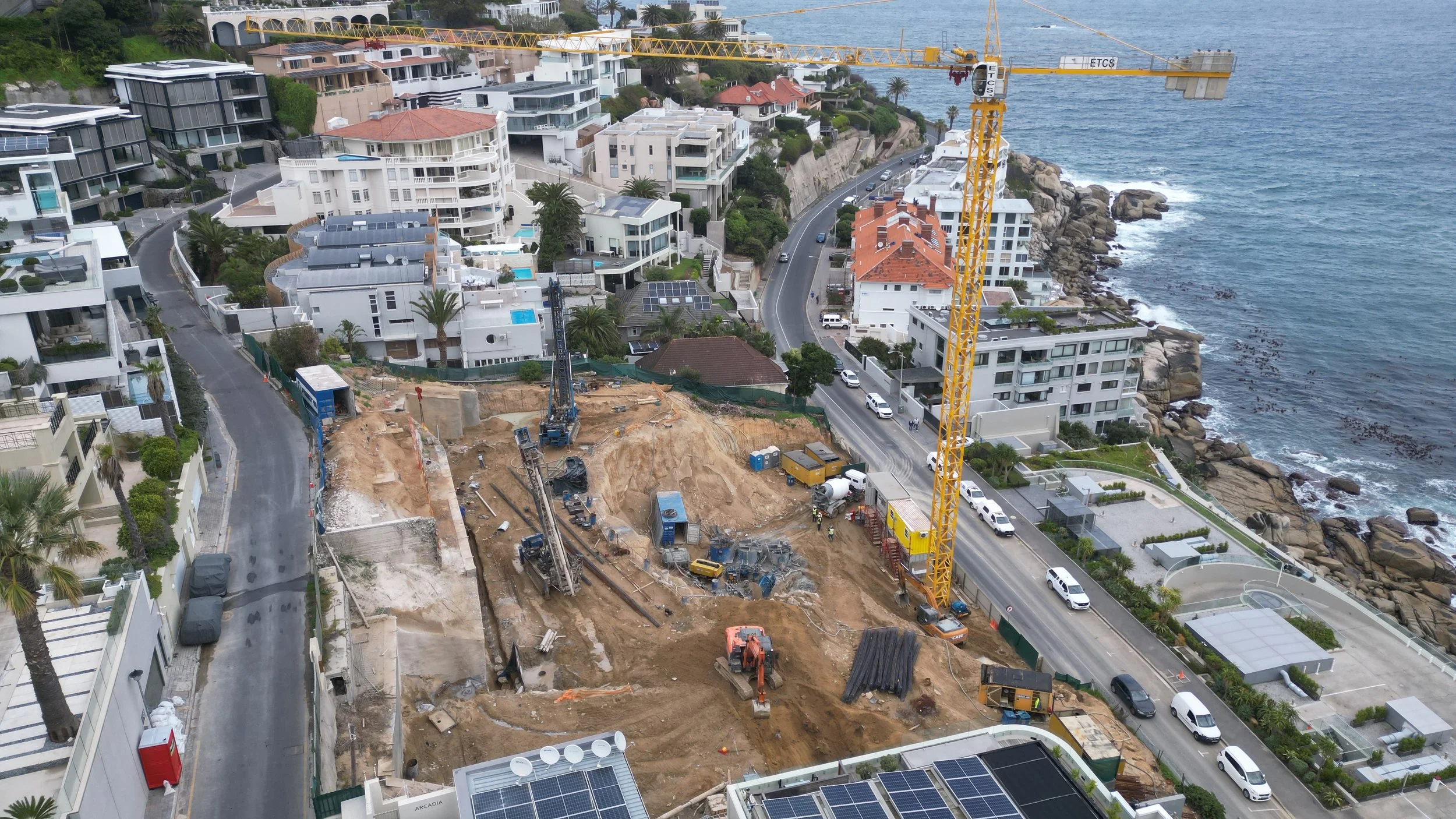
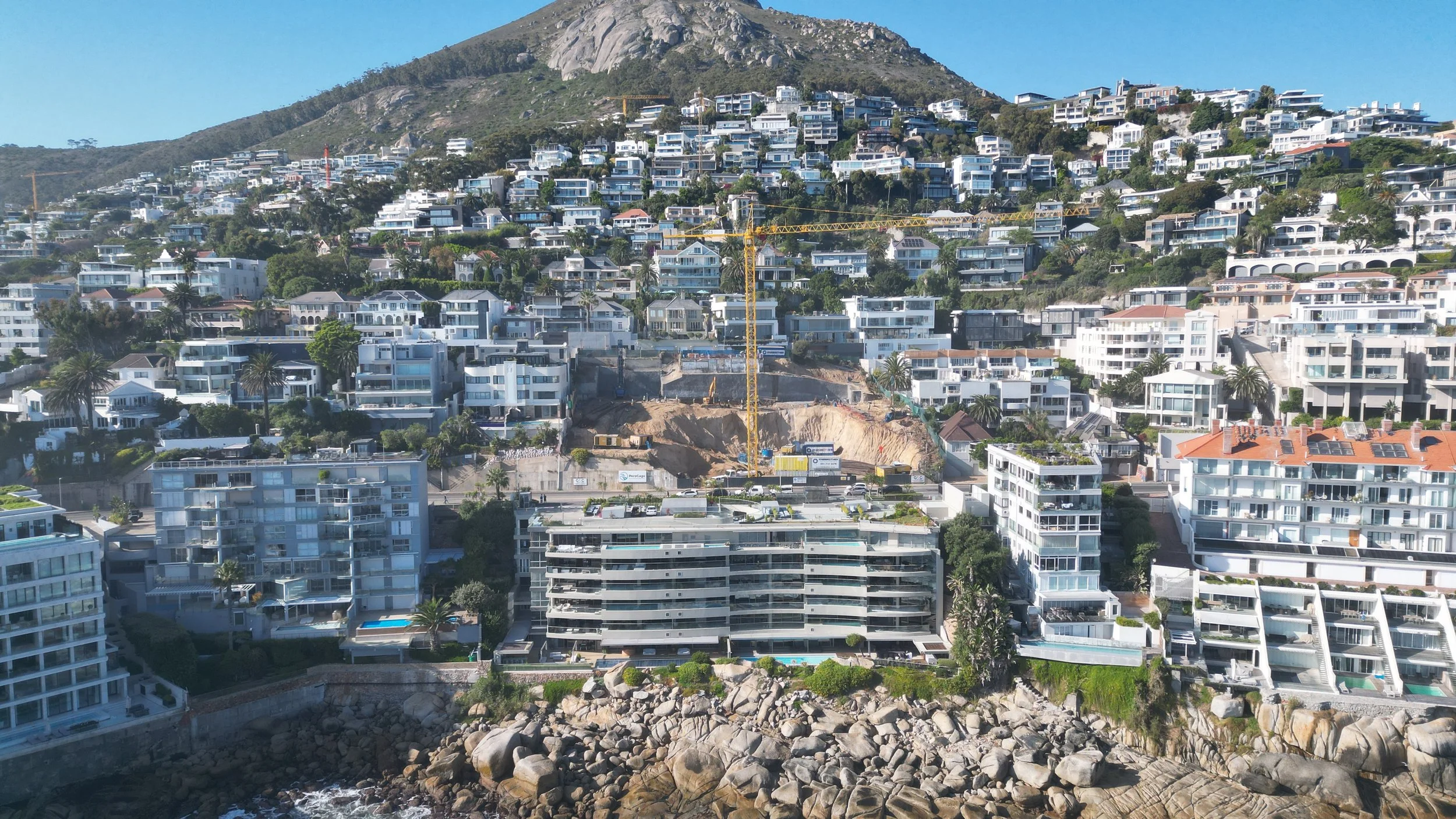
This complex lateral support project is currently in progress in Bantry Bay, Cape Town. The site is located between Ravine Road and Victoria Road, with a significant elevation difference of 25 metres. The design required an innovative solution that utilised the Ravine Road road reserve.
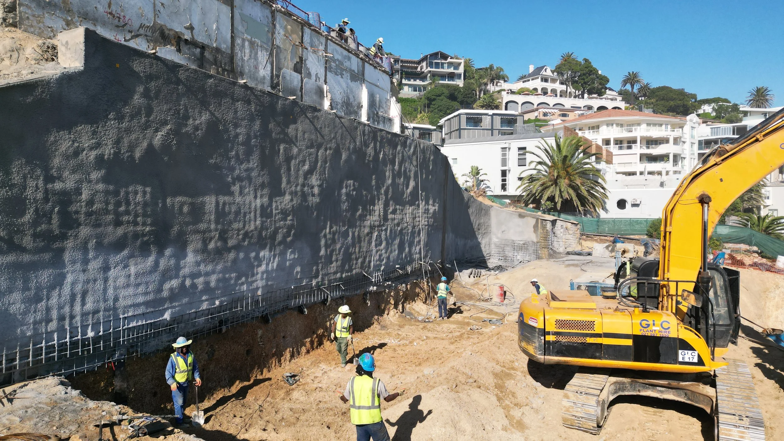
The upper 9 metres of support were constructed using untensioned soil nails and permanent shotcrete facing. Below this, a piled lateral support system with stressed anchors was introduced to manage the high ground pressures and ensure the stability of the future structure.
Scope of Work:
Permanent shotcrete – 2,580 m² installed across three sides of the excavation
Untensioned soil nails – 265 installed, from 11 m to 17 m in depth
Stressed anchors – 87 installed, up to 17 m in depth, with design loads of up to 600 kN
Lateral support piles – 181 installed, 305 mm to 406 mm in diameter to depths up to 22 m
Column piles – 78 installed, 380 mm in diameter, to depths of up to 28 m
Construction Phases
Phase 1
Includes the installation of:
935 m² of permanent shotcrete
265 untensioned soil nails
87 stressed anchors
181 lateral support piles
78 column piles
These works facilitate excavation from Ravine Road down to one level beneath Victoria Road—a total depth of approximately 25 metres.
Phase 2
Construction of the new structure progresses upward from the basement to Level 3. Each floor slab extends to the edge of the excavation and connects with the lateral support system. At Level 3, the slab spans to the site boundary and ties into the perimeter piles, forming a load transfer to the structure.
Temporary 380 mm diameter column piles support the slabs while excavation continues downward. Once the basement level is reached over the full width of the site, these temporary columns are removed and replaced with permanent structural columns built upward through each level.
Project Highlights
This project required extensive design collaboration to ensure that both temporary and permanent systems could withstand significant ground pressures while allowing for a reverse construction methodology—from top-down and then bottom-up. The result is a highly engineered solution on a challenging urban site with restricted access and boundary constraints.